
Hey, just a heads up! This post contains Amazon affiliate links, and as an Amazon Associate we earn from qualifying purchases at no additional cost to you. Thank you!
1. Overview
Our goal at High Caliber Camping is to give you all of the knowledge you need to build your camper. We know that electrical systems can feel confusing and overwhelming to work with, so we created the most intuitive, easy to follow, and free 100W camper solar wiring diagram on the internet! Continue reading to learn everything you’ll need to build a 100W solar system for your camper with enough power for all of the camping necessities.
2. Why This Setup?
Not everyone needs an intense electrical setup with an excessive power supply at their fingertips.
Maybe you do, but if you’re just looking for a simple or lightweight solar setup to power your camper wherever you go, then this is the system for you! The 100W wiring diagram below (Figure 1) shows how to wire up a single 100W solar panel, a fan, inside and outside lights, and a 5V USB charge socket to power a variety of small electronic devices.
3. 100W Camper Solar Wiring Diagram
Figure 1 below depicts the 100W solar wiring diagram. Fig 1a. shows how to connect the system, and Fig 1b. corresponds to the parts list for ease of part identification! The numbers in the black squares on Fig 1b. correspond to the “Budget-Friendly” and “Performance” part lists in Table 1 and Table 2 respectively.


Note: If you need to add or remove low-draw 12V DC accessories (such as one of the lights or the USB socket) on the 6-blade fuse block, then you can do so with minimal changes to the diagram above.
Example: if you want to add another USB socket (#12) to your setup, you could wire it in the same manner as the existing USB socket (#12) and make sure the ATC fuse in the fuse block (#8) is the correct size for your part (in this case, 5A). If you have any specific questions on your installation, please reach out to us on the contact form, or message us on Instagram!
4. Part Lists
We’ve done a lot of research to find the perfect parts for you. All items listed are components we have personally found success with in our builds – both personal and commercial. The “Budget-Friendly Part List” (Table 1) will give you the perfect intersection of cost-effective and reliable. Reference the “Performance Part List” (Table 2) if you’re looking for more efficiency and reliability, and are willing to pay a higher price tag.
Table 3 outlines a list of consumables (e.g. wire and connectors)and hardware. Table 4 names quality tools that have held up to daily use in the off road camper industry. Everything you need to build your electrical system is listed in these tables.
Table 1: Budget-Friendly Part List
| Diagram Number | Part Name | Link | Manufacturer | Quantity | Product Manual |
| 1 | 100W Rigid solar panel | Amazon Renogy | Renogy | 1 | Manual |
| 2 | 20A MC4-style Inline fuse (for Solar) | Amazon Renogy | Renogy | 2 (1 spare) | |
| 3 | Cable Entry Plate | Amazon Renogy | Renogy | 1 | Manual |
| 4 | 20A PWM Solar controller | Amazon Renogy | Renogy | 1 | Manual |
| 5 | MC4 Solar connectors with 20ft of 10Ga cable | Amazon | BougeRV | 1 | |
| 6 | 100Ah AGM battery | Amazon Renogy | Renogy | 1 | Manual |
| 7 | 20A ANL Fuse | Amazon Renogy | Renogy | 1 | Manual |
| 8 | 6-blade Fuse block | Amazon | Electop | 1 | |
| 9 | 30A Circuit breaker | Amazon | Tocas | 1 | |
| 10 | Roof fan | Amazon | Maxxair | 1 | Manual |
| (optional) | Roof fan shade (no LED) | Amazon | Maxxair | 1 | eTrailer instructions |
| 11 | LED light strip (16ft) | Amazon | Govee | 1 | |
| 12 | 5V USB Socket | Amazon | 12Vtechnology | 1 | |
| 13 | Exterior LED light | eTrailer | Optronics | 1 | |
| 14 | On-Off Power switch | Amazon | Bluesea | 3 | Manual Cutout Template |
| 15 | 3-Position Switch panel | Amazon | Bluesea | 1 | Dimensions Cutout Template (for 1 switch) |
| Overall cost: ~$860 |
|---|
Table 2: Performance Part List
| Diagram Number | Part Name | Link | Manufacturer | Quantity | Product Manual |
| 1 | 100W Flexible solar panel | Amazon Renogy | Renogy | 1 | Manual |
| 2 | 20A MC4-style Inline fuse (for Solar) | Amazon Renogy | Renogy | 2 (1 spare) | |
| 3 | Cable Entry Plate | Amazon | GoPower | 1 | |
| 4 | 15A MPPT Solar controller | Amazon | Victron | 1 | Manual |
| 5 | MC4 Solar connectors with 20ft of 10Ga cable | Amazon | BougeRV | 1 | |
| 6 | 100Ah Lithium battery | Amazon Renogy | Renogy | 1 | Manual |
| 7 | 20A Inline resettable breaker (Must have access to back of install panel. If you don’t, use #7 from the Budget-Friendly list.) | Amazon | Lumison | 1 | |
| 8 | 6-blade Fuse block | Amazon | Bluesea | 1 | Specifications Manual |
| 9 | 30A Circuit breaker | Amazon | Bluesea | 1 | Specifications Dimensions |
| 10 | Roof fan | Amazon | Maxxair | 1 | Manual |
| 11 | Warm LED light pucks | Amazon | Acegoo | 1 | |
| 12 | 5V USB socket | Amazon | Bluesea | 1 | Specifications Installation |
| 13 | Exterior LED light | eTrailer | Optronics | 1 | |
| 14 | On-Off Power switch | Amazon | Bluesea | 3 | Specifications Cutout Template |
| 15 | 3-Position Switch panel | Amazon | Bluesea | 1 | Dimensions Cutout Template (1 switch) |
| Overall cost: ~$1675 |
|---|
Table 3: Consumables and Hardware
| Part Name | Link | Manufacturer | Part Number | Quantity |
| High-quality heat-shrink electrical connector kit | Amazon | Wirefy | B07124B886 | 1 |
| ATC Fuse kit | Amazon | CrocSee | 39121600 | 1 |
| 10ft Wire loom tubing | Amazon | Alex Tech | B07TDF7P88 | 2 |
| Wire loom clamps | Amazon | Xingyheng | B01MF94YXI | 1 |
| Adhesive wire loom clamps | Amazon | Huasai | B07Z79LHJC | 1 |
| Zip ties | Zip Ties | Cable Matters | B00L2LGMO4 | 1 |
| Battery box | Battery Box | Noco | HM327BKS | 1 |
| Battery tie-down tray | Amazon | Camco | B002XL4IIO | 1 |
| Heat shrink tubing kit | Amazon | Milapeak | B071H5XC7C | 1 |
| 25ft of Red & black 10AWG wire | Amazon (Or your local hardware store) | GS Power | B0796JJHTQ | 1 |
| 100ft of Red & black 16AWG Wire | Amazon (Or your local hardware store) | GearIT | B095BZFRYY | 1 |
| ¾”-Wide & ⅛”-Thick Butyl tape | eTrailer | Alpha Systems | AL64UV | 1 |
| 3”-Wide Eternabond roof seam-sealing tape | Amazon | Eternabond | B00COGK3O6 | 1 |
| Overall cost: ~$295 |
|---|
Table 4: Tool List
| Part Name | Link | Manufacturer | Part Number | Quantity |
| Wire cutters and crimpers | Amazon | Ancor | B00T59KW1O | 1 |
| Wire strippers | Amazon | Ancor | B000NI5CMK | 1 |
| Large wire cutters and crimpers (AWG 8, 6, 4) | Amazon | IWISS | B08THKJFR9 | 1 |
| Multimeter | Amazon | Klein | B018O18VUW | 1 |
| Heat gun | Amazon | SeekOne | B078S5QMFG | 1 |
| Holesaw kit | Amazon | Bosch | HSBIM9 | 1 |
| Overall cost: ~$375 |
|---|
5. Safety
Safety Disclaimer: Electricity and electrical systems are dangerous to work on, and can easily cause injury or death when misused or handled improperly. If you don’t feel safe or confident assembling something, STOP and ask someone with experience before proceeding. Never work on live systems (e.g. a battery or solar panel that is plugged in) while alone.
All wire leads and connection posts that are connected to the battery’s positive (+) terminal/post (e.g., connected to the battery through a circuit breaker) should be considered live, and thus dangerous. Make sure to protect all possible connection posts from accidental contact with other metal objects and leads when installing the system (and when using your camper). You can protect the connection posts by wrapping electrical tape around connected leads until you are ready to install them.
If you plan on having propane in your camper, or it does not have much passive ventilation, you should add a CO/Propane alarm to your camper. This is easy to add to the 100W solar camper wiring diagram in Figure 1, as the alarm is a 12VDC component, and it will connect in the same manner as the USB socket, with 16AWG wire and a 5A fuse in the fuse block.
6. Assembly Instructions
This section outlines a step-by-step guide for installing your electrical system from the 100W solar camper electrical diagram. Before getting started, make sure you have everything you need to start your build. While not ideal, it is also perfectly okay to order things over time if you’re on a tight budget (that’s how we built our camper)!
Disclaimer: for the following preparation steps, you’ll have two wires directly connected to your battery, which can be dangerous! Take precautions to prevent the “+” and “-” wire from touching each other when they’re connected to the battery.
Preparation and Test-Fitting
- Test your Solar Controller. Directly connect two short 10AWG test wires from your solar controller to your battery via the “Battery +/-” terminals on the solar controller. Your solar controller should turn on, and you’ll be able to work through its settings to see the settings you have available.
- Test your Solar Panel. While keeping your solar panel completely covered with a blanket (or cardboard) to prevent any power output, connect it to your solar controller’s “panel” terminals with your set of 10AWG cables that have pre-installed MC4 connectors (#5 in the part list). Once you are set up, expose the solar panel to some indoor light for a few seconds. Your solar controller should start showing a small incoming charge (~0.1A) from the panel. If you’re not seeing anything come in, carefully move your setup to a space where you can expose the panel to more direct sunlight. Once you’ve verified that the panel, controller, and battery all work as expected, you can move on!
- Test fit your components. Place your components in the general location you’d like to install them. Think about how you are going to mount your components, how you will remove them for any repairs, and how the wires will route between parts. Pay special attention to your solar panel (and its cable-entry plate), fan, battery, and fuse block since these components are either large, heavy, or central to your system. If you are satisfied with your chosen locations, move on to installation!
- Mark out installation cuts for your roof fan, USB socket, solar cable entry plate, interior lights (if needed), and solar controller (if needed). Do a quick gut check for each component. Do things look like they make sense? Are you okay with having a hole in the marked locations? Can you seal the hole easily if it is on the outside of the camper? Will you be able to get wires to each component? Will you be able to access any parts for maintenance if something fails?
- Mark mounting holes for your solar panel (if needed), solar controller, solar cable entry plate, USB socket (if needed), exterior light, and roof fan. Make sure the surface the component is secured to is sturdy and can handle a screw. Start thinking about the size of screw that will be used to install each component, and how you’ll seal screws on the outside of the camper.
Installation
- Install your roof fan.
- Start out by cutting out the 14”x14” (verify this in your fan’s manual) hole (#10) in the camper’s roof. It’s a scary cut to make, but you’ll survive!
- Drill a hole inside of your planned cut area for a jigsaw blade.
- Take your time with your jigsaw to cut far-inside of the cut lines until you are completely confident in the original hole size and placement.
- If you’re completely happy with how things are going, drill small holes on the inside corners of your cut area so that your resulting cutout area will have round corners, which are stronger than square interior corners.
- Slowly widen your cut area with the jigsaw to eventually reach the full cut area, aiming for those drilled corners. Repeatedly test-fit the fan’s trim ring during this process to avoid cutting too large a hole. Aim to have the edges of the fan parallel with the sides of the camper, making sure the fan is in the right place inside of the camper.
- Add the heat-shrink electrical connectors shown in the 100W solar camper wiring diagram above to your fan’s leads. Your fan’s wires might be white (-) and black (+) instead of red (+) and black (-).
- Follow the rest of the fan install instructions in the manual that came with it (or find it linked above) to complete installing your fan!
- Note: we recommend sealing your screws by covering them with Eternabond tape instead of lap sealant. The tape is UV-stable, incredibly sticky, thick, and has excellent long term durability (5-10 years) compared to that of lap sealant (1-3 years). The tape also looks better and is less messy than lap sealant when applied correctly.
- Follow the directions included with your solar cable entry plate to install it. If it didn’t come with any instructions, use the following process.
- Cut the roof hole for your solar cable entry plate (#3) with a drill and a holesaw. Your roof cutout only needs to be large enough for your cables to enter without any extreme bends. Increase the diameter of your planned hole by ½” – ¾” to allow for some movement of the cables once installed. Just as with the fan, be methodical with your cut process to avoid any catastrophic mistakes.
- Sand/deburr the edges of your hole to remove any sharp edges that might damage your cables.
- Pass your 10AWG cables (with MC4 connectors attached) (#2) through the cable entry plate and into your camper. It is a good idea to also wrap some additional electrical tape around the cables where they pass through the roof for added insurance against abrasion from rough edges. You can opt for a cord grommet setup instead of using tape if you prefer!
- Prepare the roof surface to ensure a seal. Gently scuff the roof surface with a light abrasive, such as a steel wool pad., and clean the area with some isopropyl alcohol. Apply a single layer of butyl tape to the bottom of the cable entry plate, and place the cable entry plate against the camper roof (tip: keep the tape in the fridge until you’re ready to use it).
- Secure the cable entry plate.
- If your part has mounting holes, take a drill bit a few steps smaller than your screws, and pre-drill the mounting holes (if any). Take care to avoid drilling all the way through the roof.
- Install your sealing washers and mounting screws hand-tight, and then re-tighten them after about 30 minutes to allow the butyl tape some time to compress.
- Trim the excess butyl that squeezes out with a sharp razor blade.
- Tighten the cable gland nuts on the plate to ensure a good seal against the cables. Keep moving on!
- If your part does not have mounting holes, Tighten the cable gland nuts on the plate to ensure a good seal against the cables. Keep moving on!
- If your part has mounting holes, take a drill bit a few steps smaller than your screws, and pre-drill the mounting holes (if any). Take care to avoid drilling all the way through the roof.
- Install the solar panel on your roof and connect it to your cable entry plate! You’ll need to decide if you want to use screws or VHB tape to mount your panel. We (and many other DIYers) have found success with using 3M’s VHB tape on smooth, non-porous, and non-wood roofs.
- If you install with VHB tape, be sure to follow 3M’s instructions to increase your chances of a good install. Panel manufacturers always recommend using screws for non-flexible solar panels, and using VHB tape will likely void your panel warranty, so proceed with caution if you choose to mount with tape.
- If you install with screws you’ll want to also apply either a butyl tape or lap sealant to the bottom of the mount brackets to seal the screw hole.
- Cover the feet of the panel mounts (for hard panels) with Eternabond tape to increase the security of your seal and hold.
- Connect the inline MC4 fuse (#2) to the red (+) wire coming out of the solar panel. The MC4 connectors will give a solid “click” when they are fully connected.
- Connect the MC4 leads coming off of the panel (now including the fuse) to the MC4 cables (#5) coming out of the cable entry port that you prepped in the previous step. Match red (+) to red (+) and black (-) to black (-). Remove any extra slack from the cables on your roof, and your panel install will be complete.
- Mount the battery to your camper.
- If you plan to keep the battery inside your camper, it needs to be placed inside of a battery box that vents outside of the camper. This is for two reasons, 1). to vent any Hydrogen battery gas (lead-acid batteries vent Hydrogen gas when overcharged), and 2) to keep any potential electrical sparks away from the battery.
- If you put the battery outside of the camper, just place the battery in a covered battery box that is secured to the camper frame. Make sure the battery itself is secured as well. Temporarily cover the battery terminals with cardboard or tape to prevent accidental contact during assembly.
- Install the 20A ANL fuse (#7) between your battery’s positive terminal and your solar controller. Allow enough space on either end of the fuse for a gentle wire bend to avoid any cable and connector fatigue. Don’t connect any wires to it just yet.
- Install your solar controller in the camper.
- Mark the place where you want to install your solar controller by holding the part against the install surface and tracing in the mount holes with a pencil or sharpie. Double check that there is some room around the solar controller for running the wires into it.
- If your solar controller’s terminals are not accessible when it is installed (like the Renogy controller we recommend), you may want to first connect your battery wires (making sure to run the positive line from the 20A ANL fuse (#7)), and then your solar panel wires to the solar controller before mounting the part. This way you can avoid having to unmount the controller to connect the wires. If you do this, avoid connecting the battery-end of the wires until the very end of the install to prevent accidentally creating a short when installing something.
- Be careful at this step, because if you mix up the positive and negative terminals, you can cause reverse polarity and a short, which could damage the panel and controller.
- If your solar controller’s terminals are accessible while installed, wait to connect it along with the rest of your wires at the end of your install process.
- Mount the 30A circuit breaker (#9) that goes between the battery and fuse block. Our listed component does not require any specific end to be connected to the battery, but other brands may. Make sure to check the manual for your circuit breaker. Keep the protection caps on the terminal screws, as you’ll need those later.
- Mount your fuse block (#8). Before mounting the fuse block, preinstall the ATC fuses so that you don’t forget to put them in later.
- Mount your switch panel (#15).
- Double check the hole that you marked in the preparation stage.
- Cut a hole for your switch panel using a jigsaw or a router. Just like the cuts for the roof fan, you’ll want to start small and work your way out to the marked line to avoid cutting a hole that is too large. Test-fit the panel as you go.
- Press-fit the switch panel into the hole.
- Press the switches (#14) into your switch panel. Take a picture of the markings on the back of the switches so you know where to connect your wires later on.
- Install your USB socket (#12).
- Double check the hole that you marked in the preparation stage.
- Cut a hole for your USB socket using a router, a jigsaw, or a holesaw. Note that some of the cutout holes are not fully circular, so take extra care to not cut your hole too large.
- Install your socket in the cut hole. Depending upon your mount method, either screw its nut and thread compression device tight, or screw in the face panel.
- Install your exterior light (#13). Pick a spot for your light on the outside of your camper. Higher is better because it will cast the light over a larger area and reduce the light intensity in any one spot. Think about different placements before you commit to your final location. Once you’re sure about your install spot, move on to installation.
- Drill and sand/deburr a hole that is large enough to fit both of your light’s wires through.
- Wrap the part of the wires closest to the light in some electrical tape to give them some additional abrasion protection.
- Attach the seal to the back of your light and screw it into your camper.
- Install your interior light (#11). For our camper we chose to place our LED strip inside of our fan shade, which provided enough gentle light at night to help us see without being overwhelming. This approach also really simplified the installation process because the light was effectively built into the fan shade. We’ll have an article coming on this down the road.
- If you’re using an LED strip:
- Cut off the plug that is provided with the LED kit, making sure to leave as much wire as possible attached to the LED end.
- Strip and separate the ends of the remaining wires.
- Crimp on spade electrical ends as shown in the 100W solar camper wiring diagram (Figure 1a).
- Mount your LED strip somewhere hidden from view, and in a place where the light it gives off is well diffused. Make sure the wire leads are still accessible later.
- If you’re using LED puck lights:
- Find a place to put the lights in the camper’s ceiling. You have the choice of making the lights protrude from the ceiling, or recessing the lights in the ceiling. The former is easy to achieve, but hiding the wires that run to the lights will be difficult. The latter can be achieved by installing tongue and groove panels on the ceiling and contouring the panels to fit the lights and their wires. It is a lot of work, but also looks fantastic.
- You’ll need to modify the 100W solar camper wiring diagram a bit. Wire the lights in parallel with each other so that they all have the same voltage and brightness.
- Strip and separate the ends of the wires.
- Crimp on spade electrical ends as shown in the wiring diagram (Figure 1a).
- Mount your puck lights with the provided clips or screws. Make sure the wire leads are still accessible later. If you’re installing these recessed in the roof, you may want to run the wires to your battery prior to finally installing the puck lights in the ceiling.
- If you’re using an LED strip:
- Connect wires to components.
- Starting with your 12VDC components, build your wiring harness as shown in the wiring diagram (Figure 1a). Move through your harness one by one, ending with the connections to your battery (but don’t connect them yet!).
- Cut, crimp, and heatshrink each end that has an electrical connector shown in the wiring diagram. We recommend using spade connectors instead of butt connectors when going to components because it will make replacing a broken or faulty component much easier in the future. Cover your wire runs with trim or wire raceway as-needed. Alternatively, you can hide wire behind some tongue and groove wood interior panels, or even use a synthetic wire sleeve for an industrial look.
- Double-check your wire harness and connections against the wiring diagram.
- Connect the main leads to the battery once you’re confident that everything looks good!
- Test the 20A circuit breaker (#7) between your battery and fuse block. Make sure that no power is delivered to the 12VDC components when the circuit breaker is off. This circuit breaker will be your main “off” switch when putting the camper in storage.
Troubleshoot any issues that you find with your system. If you have any specific issues that you can’t find answers to – please ask on the contact form, or message us on Instagram, and we’ll be happy to help!
7. Additional Notes
Wire, fuse, and circuit breaker sizes: Simply put, wires are sized to supply the required power to a component for long durations of time without catching on fire. Fuses and circuit breakers are sized to prevent a wire from drawing power above the wire’s rated current for long enough to catch fire. The size of your wire gauge will also be determined by the length of wire that you are running between connections. This guide and 100W solar camper wiring diagram assume that you are running lengths of less than 20ft of wire between each connection, which is a fairly safe bet for most DIY campers. Bluesea has a fantastic DC wire sizing chart that you can use to easily find your wire sizes if you have longer run lengths or want to learn more.
So, the order of size determination is: component amperage draw -> wire size -> fuse size. For the type of wire to use, pure stranded Copper wire is always preferred. Copper cladded aluminum wire (CCA) is rated for lower currents than pure Copper wire. Never use solid core wire in your system, as it is not designed to be used in the high vibration environments a camper will experience. Here’s a simple guide on the differences between the two types of wire. The insulation material of wire can also vary wildly – look for insulation that is heat rated to +105°C (it will be printed on the insulation). Always buy your wire and fuses from a reputable electrical supplier. We have found PowerWerx to be a reliable online dealer if you cannot find a local supply. Don’t cheap-out on wire!
Batteries: When choosing a battery, you’ll primarily have the option of sealed AGM (Acid Glass Mat) or Lithium. The two types couldn’t be more different, but there are only a few key considerations you need to make.
- Lithium batteries won’t charge if they are exposed to below freezing temperatures. This means that they must be actively heated or insulated from the cold to charge.
- AGM batteries have a lower functional discharge depth. If you had a 100Ah AGM battery and a 100Ah Lithium battery, you can only safely discharge the AGM battery to about 50Ah without damaging the battery. The Lithium battery would easily handle discharging down to 10-15Ah before needing to recharge.
- Lithium batteries are nearly 3-4 times as expensive as AGM batteries.
- Lithium batteries do not need to vent gasses, so they can be kept inside of a camper without running a gas hose to the outside wall. HOWEVER, Lithium batteries still do need to cool down during use to prevent thermal runaway, so ventilation of the battery to maintain its low temperature is important.
If you need excellent depth of discharge and more fancy features, a Lithium battery will be the way to go. If you want a cost-effective system, and are willing to accommodate the extra quirks of AGM batteries, then they will be the perfect solution for you.
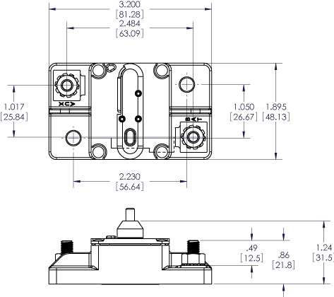
Types of Circuit Breakers: For your resettable circuit breakers you have the option of choosing either “surface” mount or “panel” mount style. The “surface” mount type (Fig. 2a) will allow the breaker to be mounted directly onto a wall without drilling any holes through the wall (besides the holes for screwing it to the wall). The connecting wires will sit on the same side of the wall as the breaker switch. The “panel” mount type (Fig. 2b) requires a hole to be cut in the wall to accommodate the body of the breaker. This type of breaker is designed to be used where the connecting wires are on the opposite side of the wall of the switch. It offers a visually clean design, but requires more work, forethought, a wall that can be cut out. The easiest option to install will almost always be a surface mount breaker.


Share your build pictures with us to be featured on our Instagram!
We created this website with the goal of inspiring you to go out and build the camper of your dreams. If you have any questions at all, or build something cool, we’d love to see it! Please reach out through our contact form or our Instagram!